Building a Turboencabulator
The source material
The text is older than the sheet. It was written by a British engineering student, John Hellins Quick, and published in 1944 in the student journal of the Institution of Electrical Engineers; Time quoted it in April 1946, in a piece called “For Nofer Trunnions”, and it has been passed around (and performed, straight-faced, on film) ever since. The version I worked from is GE handbook sheet HBK-8359, dated December 31, 1962, which dresses the joke up as a real product listing.
- John Hellins Quick's “The Turbo-Encabulator in Industry”, in the IEE's Students' Quarterly Journal
- Reprinted in the U.S. by Arthur D. Little, Inc. in its Industrial Bulletin
- Time runs it as “For Nofer Trunnions”
- General Electric's Instrument Department issues handbook sheet HBK-8359
- Bud Haggart performs it, straight-faced, in an industrial film
- Haggart films it again for Chrysler, as if Chrysler had built it
- Rockwell Automation's “Retro Encabulator”, narrated by Mike Kraft, using an Allen-Bradley motor control centre
- Mike Kraft narrates the SANS ICS “HyperEncabulator”
- This one: in 3D, with forty-seven pluckable brushes
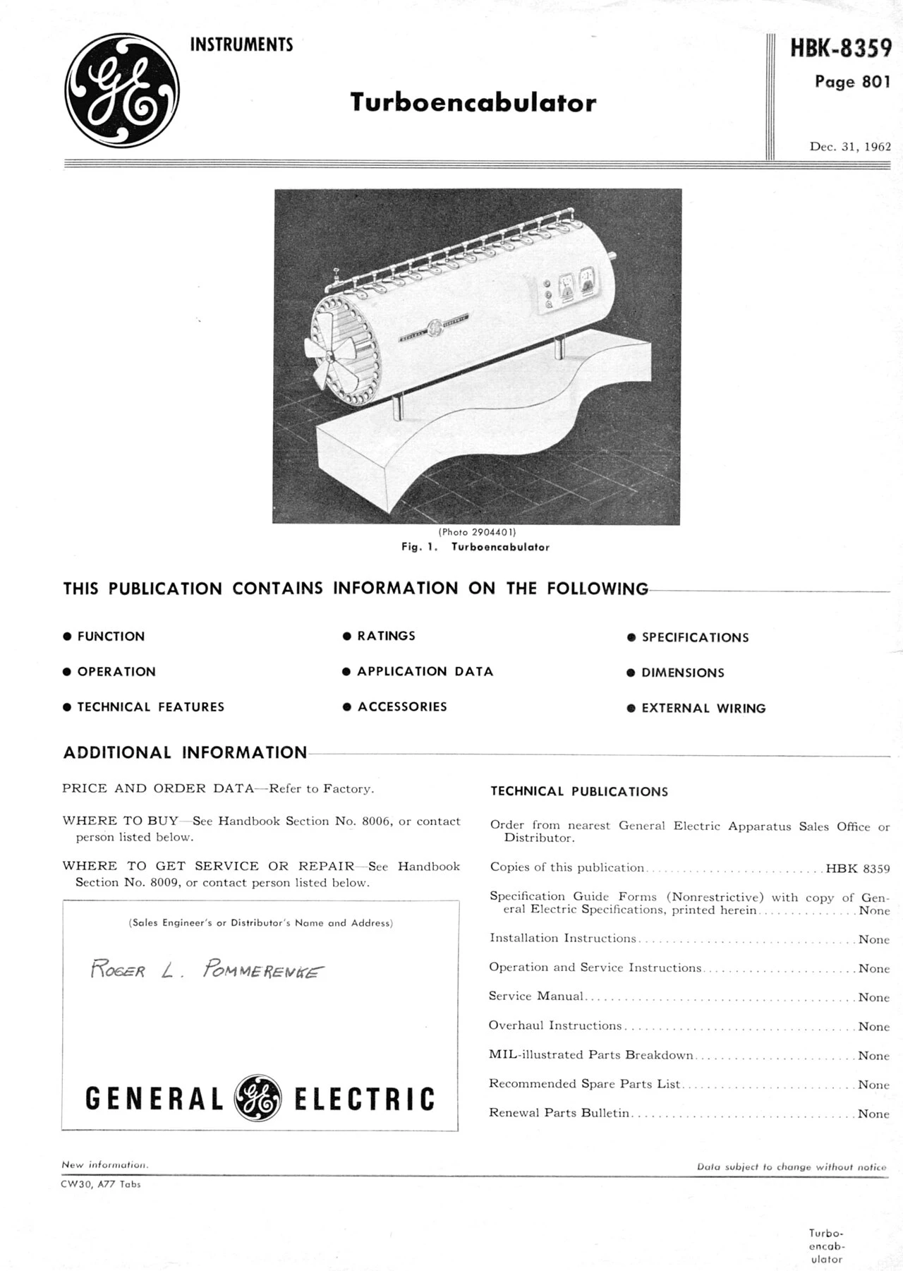
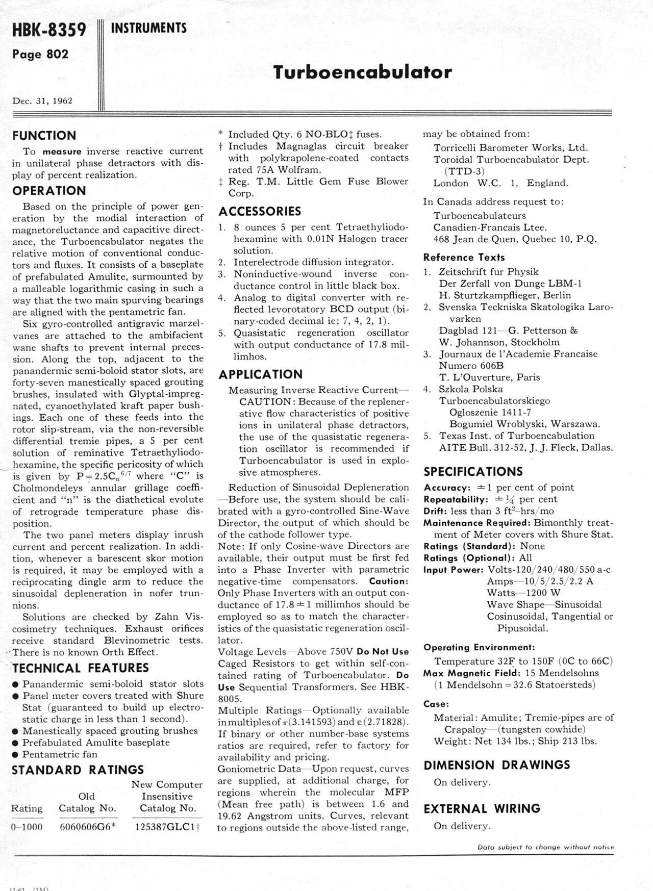
That last detail sets the terms of the project. There are no blueprints, so everything is reverse-engineered from Fig. 1, a single grainy photo, and the sheet's descriptions of parts that don't exist. The photo turns out to be enough. The machine is a handful of simple solids:
| Datasheet part | In Fig. 1 | Built from |
|---|---|---|
| Malleable logarithmic casing | The long drum | Open cylinder + end cap |
| Pentametric fan | Six blades on the intake | Squashed spheres, pitched |
| Semi-boloid stator slots | Ring of tubes round the fan | 30 instanced cylinders |
| Grouting brushes ×47 | The comb of loops on top | Half-torus arches + tufts |
| Tremie pipes | The rail above them | A thin cylinder, valve at one end |
| Panel meters | Two dials, three buttons | Rounded boxes, canvas-drawn dials |
| Prefabulated Amulite baseplate | The S-curved plinth | An extruded sine-edged shape |
| Lotus-o-delta main winding | Hidden inside the drum | 21 swept helix turns, every seventh in gold |
| Differential girdle spring | Hidden inside the drum | A swept spiral that winds with the drive |
Each part is a THREE.Group built in its assembled position, plus two extra numbers: an explode vector (where it goes when the machine comes apart) and an anchor (where its label's leader line attaches). Assembled is always the origin, so exploding is just tweening each group's position to its vector.
Drawing it like a comic
The look comes from Raj Shekhar's Voyager, which renders the spacecraft like a page from a technical comic: a few flat colours, heavy ink outlines and shading done with halftone dots. Three tricks get you most of the way there.
1 · Three tones, two of them dots
Each surface gets one flat palette colour. The fragment shader compares the surface normal with a light direction: lit faces keep the flat colour, faces turning away get a screen of slightly darker dots, and faces in shadow get ink dots. The dots are laid out in screen space on a 45° grid, as in print, so they stay the same size however close you zoom. Try it:
float l = dot(n, uLight);
    vec3 c = uBase;
    if (l < 0.3)   c = mix(uBase, uBase * 0.7, screen(r));    // mid-tone dots
    if (l < -0.12) c = mix(uBase * 0.78, uInk, screen(0.38)); // ink dots
The light is fixed relative to the camera, not the world, so the shading reads like a drawing as you orbit, rather than like an object turning under a lamp.
2 · Ink outlines from an inverted hull
Every mesh gets a twin drawn with only its back faces, pushed outwards so its rim peeks out around the silhouette as a dark line. The push happens in the vertex shader, in pixels, so the line keeps the same weight at any distance. Hard-edged geometry like a cylinder's cap has split normals that would crack the hull at the corners, so each vertex is pushed along the average normal of every vertex at the same position.
vec4 clip = projectionMatrix * modelViewMatrix * vec4(pos, 1.0);
    vec4 nc   = projectionMatrix * modelViewMatrix * vec4(pos + outNormal * 0.01, 1.0);
    vec2 d = (nc.xy / nc.w - clip.xy / clip.w) * uView;            // normal, in pixels
    clip.xy += normalize(d) * uLine * 2.0 / uView * clip.w;          // push uLine px out
3 · Fade through the dots
Parts don't fade in with transparency; they dissolve through the same dot screen, each dot shrinking from nothing. It's one line in the fragment shader, and it keeps the intro in the printed-page idiom.
Choreography with anime.js
anime.js is usually pointed at DOM elements, but it will animate any plain JavaScript object, which means it can drive a 3D scene directly: mesh.position, a shader uniform's value, or a state object the render loop reads. The whole machine is one such object, and engaging it is a timeline:
createTimeline()
      .add(lamps, { g: [0, 1], delay: stagger(160) }, 0)          // lamps light in turn
      .add(S, { inrush: 1, ease: 'outExpo' }, 520)                // inrush spike…
      .add(S, { inrush: 0.62, ease: 'outElastic(1, .35)' }, 940)  // …settles with a wobble
      .add(S, { rpm: 1, duration: 2800 }, 600)                    // fan spins up
      .add(S, { realization: 0.874, ease: 'outQuart' }, 1100);
stagger() does the rest: parts assemble one after another in the intro, the 47 brushes drop in with a bounce, and labels pop in down the list when you explode the machine.
Forty-seven brushes on a string
At first the brushes simply bobbed in a travelling sine wave, which looked nice and meant nothing. Now each brush is a mass tied to its neighbours, which makes the row a discretized vibrating string:
u is each brush's height, c the wave speed (about 30 brushes a second), γ the damping (the Viscosity slider) and k a weak pull back to rest. The ends are imaginary brushes: leave one at zero and the string is pinned there, so waves reflect; move one to a waveform and that end is driven. That's all the wave-shape selector does. Integration is semi-implicit Euler at 240 steps a second, which keeps c·h well under 1, the limit past which the string explodes. Here's the same string, flat:
Grabbing a brush in 3D needed one more trick. The brushes are a few pixels wide, so instead of asking the ray to hit one, the code finds where the pointer's ray passes closest to the whole row of brushes, and accepts anything within a brush-width or so (as long as the casing isn't in the way). Dragging then happens on a vertical plane facing the camera, so up always means up.
Wave shapes have consequences
The datasheet has opinions about waveforms, so the selector does more than reshape the drive:
| Shape | What happens |
|---|---|
| Sinusoidal | Nominal. Realization settles at 87.4%. |
| Cosinusoidal | Drives from the opposite end. The sheet says cosine-wave directors must feed a Phase Inverter first, so until you fit one the drive is garbled, the amber lamp blinks and realization collapses to 31%. |
| Tangential | Every asymptote pegs the inrush needle, rattles the tremie pipes and flashes the red lamp. |
| Pipusoidal | The pentametric fan surges on each pip, and the machine shudders with it. |